About Electronic Optocouplers IC
Backed by a team of experts, we have been a respected supplier of Electronic Optocouplers IC in the market. This can either be used on their own as a switching device, or used with other electronic devices to provide isolation between low and high voltage circuits. Electronic Optocouplers IC can be availed from us at affordable rates.
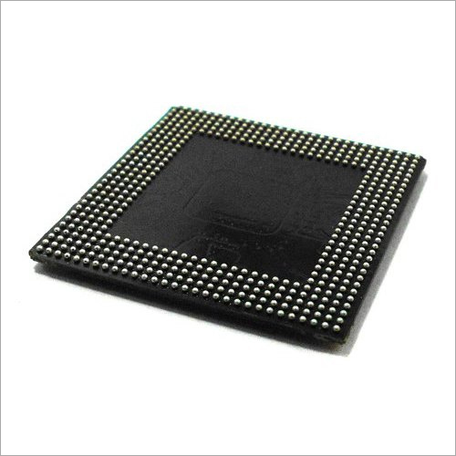
Type | Non-Leaded |
Temperature | 0 - 175 Degree C |
Voltage | 120 VAC |
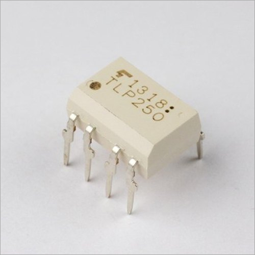
Model Name/Number | TLP 250 |
Frequency | 50 Hz |
Current | 5 - 10 amp |
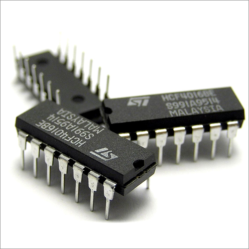
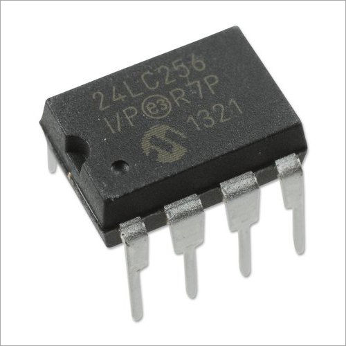
These optocoupler ICs employ internal LED and phototransistor/photodarlington circuits to achieve signal isolation of up to 5000 Vrms. This mechanism ensures that control systems and sensitive microprocessors remain protected from electrical spikes, thus enhancing system reliability and longevity. Their modern packages enable both through-hole and surface mounting, accommodating various PCB design requirements.
Versatile Applications Across IndustriesWith their high isolation voltage, rapid response times (as quick as 0.1 s), and low input current requirements, these optocouplers are ideal for microcontroller interfaces, switching control, and power supply monitoring. They cater to applications in automation, industrial control, power electronics, and integrated circuits, supporting both signal and data transmission with electrical isolation.
FAQ's of Electronic Optocouplers IC:
Q: How does the optocoupler IC provide electrical isolation between input and output signals?
A: The optocoupler IC uses an internal LED and phototransistor (or photodarlington) separated by a transparent barrier. When the LED is energized, it emits light detected by the phototransistor, transferring the signal without any physical electrical connection. This ensures high-voltage isolation (5000 Vrms typical) between input and output circuits.
Q: What are the main benefits of using electronic optocouplers in microcontroller interfaces?
A: Optocouplers protect microcontroller circuits from voltage transients, noise, and ground loops by isolating low-voltage control circuitry from high-voltage or noisy environments. They also allow safe switching of signals, reducing the risk of damage or malfunction due to electrical interference.
Q: When should I use a single-channel versus a dual-channel optocoupler IC?
A: Single-channel optocouplers are ideal for isolating individual control lines, while dual-channel types are beneficial when two signals need simultaneous isolation, such as transmitting differential signals or controlling multiple relays from a single IC, simplifying circuit design and saving board space.
Q: Where are optocoupler ICs typically installed in electronic systems?
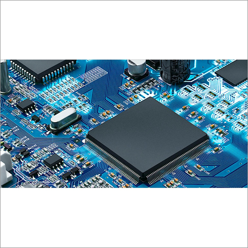
A: Optocouplers are mounted on PCBs using through-hole or SMD techniques. They appear in input/output sections of power supplies, microcontroller circuits, switching devices, and interface modules, particularly where galvanic isolation is critical for system protection.
Q: What is the recommended process to connect optocoupler ICs in a circuit?
A: Connect the input LED side to the control signal, ensuring appropriate current-limiting resistors (typically supporting 10-20 mA). Power the output phototransistor with an external supply as per your application's voltage (5V typical) and connect the output to the receiving device, observing maximum ratings for voltage and current.
Q: What usage considerations should be checked when choosing an optocoupler for a new project?
A: Check the required isolation voltage, number of channels, collector-emitter voltage, mounting style (SMD or through-hole), and current rating. Also, consider pin pitch (2.54 mm in DIP), operational frequency, power supply compatibility, and the need for RoHS compliance in your application.


 Send Inquiry
 Send Inquiry
 Send SMS